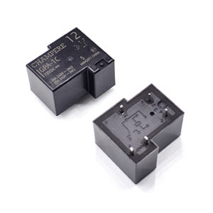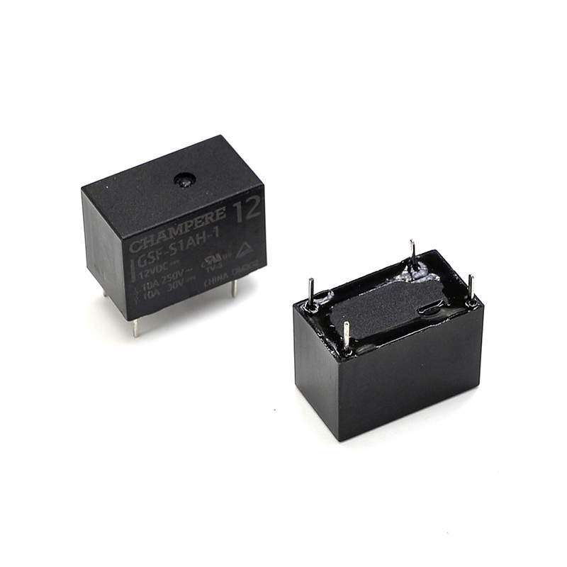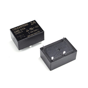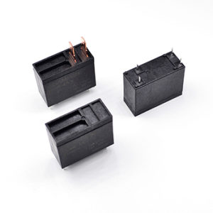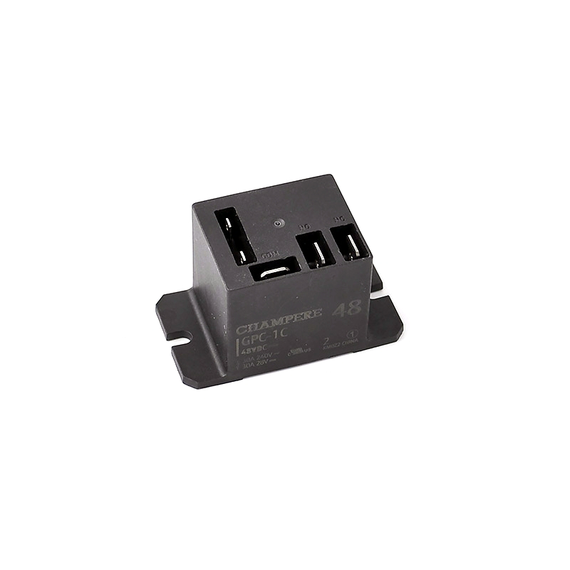
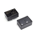
GMR Series
Price range: 12 Amp through 20 Amp Rating
- 28.8 x 12.5 x 15.5(H) mm.
- 20A Max Switching Capacity, Suitable for Complex Load.
- Available in 1 & 2 Poles and Dielectric Strength > 5KV.
- Class F Insulation and Glow Wire Version Available.
- Certified with


- CONTACT & COIL
- CHARACTERISTICS
- Model Info.
- Dimensions
- Precautions
Description
| CONTACT RATINGS | |||
|---|---|---|---|
| Contact Form | 1A, 1B, 1C, 2A, 2B, 2C | ||
| Contact Res. | ≤100mΩ | ||
| Contact Material | Ag Alloy (AgSnO2, AgSnO2In2O3, AgNi) | ||
| Rated Load | FORM A | FORM C | |
| NO | NC | ||
| 20A 277VAC(1A) 16A 30VDC(1A) 12A 250VAC(2A) 8A 30VDC(2A) |
20A 277VAC(1C) 16A 30VDC(1C) 12A 250VAC(2C) 8A 30VDC(2C) |
16A 277VAC(1C) 16A 30VDC(1C) 8A 277VAC(2C) 8A 30VDC(2C) |
|
| Max. Current | 20A (1 Pole) 12A (2 Poles) |
16A (1 Pole) 8A (2 Poles) |
|
| Max. Power | 5,540VA/480W (1 Pole) 3,000VA/240W (2 Poles) |
4,432VA/480W (1 Pole) 2,216VA/240W (2 Poles) |
|
| Max. Voltage | 277VAC/30VDC | ||
| Min. Load | 100mA at 5VDC | ||
| COIL DATA | |||||
|---|---|---|---|---|---|
| DC STANDARD | Approx. 400mW | ||||
| Rated Voltage (VDC) | Operate Voltage (VDC) | Release Voltage (VDC) | Max. Voltage (VDC) | Nominal Current (mA) | Coil Res. (Ω)±10% |
| 5 | ≤3.75 | ≥0.25 | 6.5 | 80 | 62.6 |
| 9 | ≤6.75 | ≥0.45 | 11.7 | 44.4 | 202.5 |
| 12 | ≤9 | ≥0.6 | 15.6 | 33.3 | 360 |
| 24 | ≤18 | ≥1.2 | 31.2 | 16.7 | 1,440 |
| 48 | ≤36 | ≥2.4 | 62.4 | 8.3 | 5,760 |
| 110 | ≤82.5 | ≥5.5 | 143 | 3.64 | 30,250 |
| DC SENSITIVE | Approx. 250mW | ||||
| Rated Voltage (VDC) | Operate Voltage (VDC) | Release Voltage (VDC) | Max. Voltage (VDC) | Nominal Current (mA) | Coil Res. (Ω)±10% |
| 5 | ≤4 | ≥0.25 | 6.5 | 50 | 100 |
| 9 | ≤7.2 | ≥0.45 | 11.7 | 27.8 | 324 |
| 12 | ≤9.6 | ≥0.6 | 15.6 | 20.8 | 576 |
| 24 | ≤19.2 | ≥1.2 | 31.2 | 10.4 | 2,304 |
| 48 | ≤38.4 | ≥2.4 | 62.4 | 5.2 | 9,216 |
| 60 | ≤45 | ≥3 | 78 | 4.17 | 14,400 |
| AC COIL | Approx. 0.75VA | ||||
| Rated Voltage (VAC) | Operate Voltage (VAC) | Release Voltage (VAC) | Max. Voltage (VAC) | Nominal Current (mA) | Coil Res. (Ω)±10% |
| 24 | ≤19.2 | ≥3.6 | 31.2 | 31.6 | 350 |
| 110/115 | ≤92 | ≥17.3 | 143 | 6.6 | 8,100 |
| 220/230 | ≤184 | ≥34.5 | 286 | 3.2 | 32,500 |
Additional information
| Weight | 13 g |
|---|---|
| Dimensions | 28.8 × 12.5 × 15.5 mm |
| Certified Approval | cULus, TUV, UL TV-8 |
| Max. Capacity | 12A 250VAC, 20A 277VAC |
| Contact Form | 1 Form A, 1 Form B, 1 Form C, 2 Form A, 2 Form B, 2 Form C |
| Operate Time | ≤15ms |
| Release Time | ≤10ms |
| Coil Power | 0.25W, 0.4W |
| Insulation Resistance | 1,000MΩ (@500VDC) |
| Dielectric Strength (I/O) | 5,000VAC 1min |
| Dielectric Strength (O/O) | 1,000VAC 1min |
| Creepage Distance | >8mm |
| Shock Resistance | Non-energized: 10G; Destructiion: 100G; Malfunction: 10G |
| Vibration Resistance | Destruction: 10 to 55Hz (Double Amplitude); Malfunction: 10 to 55Hz (Double Amplitude) |
| Ambient Temperature | Operating: -40℃ – 105℃ |
| Ambient Humidity | Operating: 5% – 85% |
| Mount Type | PCB Pin (DIP/TH) |
| Pin Pitch | 3.5mm, 5mm |
| Color | Black |
| Model Number Legend | ||||||||||||||
|---|---|---|---|---|---|---|---|---|---|---|---|---|---|---|
| GMR | – | S | 1 | A | Q | – | L | F | 2 | – | XXX | / | 24VDC | |
| (1) | (2) | (3) | (4) | (5) | (6) | (7) | (8) | (9) | ||||||
| (1) | Enclosure Rating: | Nil: Flux Proof; S: Plastic Sealed. | ||||||||||||
| (2) | NO of Pole: | 1: Single Pole; 2: Double Pole. | ||||||||||||
| (3) | Contact Form: | A: Form A / Normally Open; B: Form B / Normally Close; C: Form C / Change Over. | ||||||||||||
| (4) | Contact Material: | Nil: Silver Alloy (ROHS Complaint); D: AgCdO; Q: AgNi for Cont. Current. | ||||||||||||
| (5) | Power Consumption: | Nil: Standard Coil (0.4W); K: Sensitive Coil (0.25W). | ||||||||||||
| (6) | Insulation Class: | Nil: Standard Insulation; F: Class F Insulation. | ||||||||||||
| (7) | Pin Pitch: | 1: 3.5mm; 2: 5mm. | ||||||||||||
| (8) | Customer Code: | XXX: Customer Code, not Related to Construction. | ||||||||||||
| (9) | Coil Voltage: | X / XX VDC: DC Coil Voltage Value. | ||||||||||||
| Major Model Ordering Chart | ||||||
|---|---|---|---|---|---|---|
| Enclosure Rating | Contact Form | Capacity | Coil Power | Pin Pitch | Model | Coil Voltage |
| Flux Proof | SPST | NO: 20A NC: 16A (if applicable) |
0.4W | 5mm | GMR-1A-2 | 5VDC 6VDC 9VDC 12VDC 24VDC 48VDC 60VDC 110VDC |
| 0.25W | GMR-1A-L2 | |||||
| SPDT | 0.4W | GMR-1C-2 | ||||
| 0.25W | GMN-1C-L2 | |||||
| Fully Sealed | SPST | 0.4W | GMR-S1A-2 | |||
| 0.25W | GMR-S1A-L2 | |||||
| SPDT | 0.4W | GMR-S1C-2 | ||||
| 0.25W | GMR-S1C-L2 | |||||
| Flux Proof | DPST | NO: 12A NC: 8A (if applicable) |
0.4W | GMR-2A-2 | ||
| 0.25W | GMR-2A-L2 | |||||
| DPDT | 0.4W | GMR-2C-2 | ||||
| 0.25W | GMR-2C-L2 | |||||
| Fully Sealed | DPST | 0.4W | GMR-S2A-2 | |||
| 0.25W | GMR-S2A-L2 | |||||
| DPDT | 0.4W | GMR-S2C-2 | ||||
| 0.25W | GMR-S2C-L2 | |||||
| Flux Proof | SPST | NO: 20A NC: 16A (if applicable) |
0.4W | 3.5mm | GMR-1A-1 | |
| 0.25W | GMR-1A-L1 | |||||
| SPDT | 0.4W | GMR-1C-1 | ||||
| 0.25W | GMR-1C-L1 | |||||
| Fully Sealed | SPST | 0.4W | GMR-S1A-1 | |||
| 0.25W | GMR-S1A-L1 | |||||
| SPDT | 0.4W | GMR-S1C-1 | ||||
| 0.25W | GMR-S1C-L1 | |||||
For high power type, we suggest to select flux proof version for better heat distribution if the relay will not exposed in high humidity/sulphide/dust environment.
For standard type, materials used already meet Class F insulation requirements.
When ordering, add rated coil voltage to model.


PRECAUTIONS REGARDING COIL INPUT
For the operation of AC relays, the power source is almost always a commercial frequency (50 or 60 Hz) with standard voltages of 6, 12, 24, 48, 120, 230 and 240VAC. Due to this, when the voltage is ohter than the standard voltage, the product becomes special model.
PRECAUTIONS REGARDING CONTACT
For the operation of AC relays, the power source is almost always a commercial frequency (50 or 60 Hz) with standard voltages of 6, 12, 24, 48, 120, 230 and 240VAC. Due to this, when the voltage is ohter than the standard voltage, the product becomes special model.
PRECAUTIONS REGARDING SOLDERING CONDITION
We recommend wave solder, the recommended temperature is 240°C 464°F to 260°C 500°F, and the time is 2s to 5s, time should no longer than 2s when temperature reach 250°C 500°F or above.